CONSTRUCT & CREATE Hydraulic Robot Arm
FREE Shipping
CONSTRUCT & CREATE Hydraulic Robot Arm
- Brand: Unbranded

Description
Liquids in motion or under pressure did useful work for humanity for many centuries before French scientist-philosopher Blaise Pascal and Swiss physicist Daniel Bernoulli formulated the laws on which modern hydraulic power technology is based. Pascal’s principle, formulated about 1650, states that pressure in a liquid is transmitted equally in all directions; i.e, when water is made to fill a closed container, the application of pressure at any point will be transmitted to all sides of the container. In the hydraulic press, Pascal’s principle is used to gain an increase in force; a small force applied to a small piston in a small cylinder is transmitted through a tube to a large cylinder, where it presses equally against all sides of the cylinder, including the large piston. There are a number of standardized methods in use to attach the hose or tube to the component. Some are intended for ease of use and service, others are better for higher system pressures or control of leakage. The most common method, in general, is to provide in each component a female-threaded port, on each hose or tube a female-threaded captive nut, and use a separate adapter fitting with matching male threads to connect the two. This is functional, economical to manufacture, and easy to service.
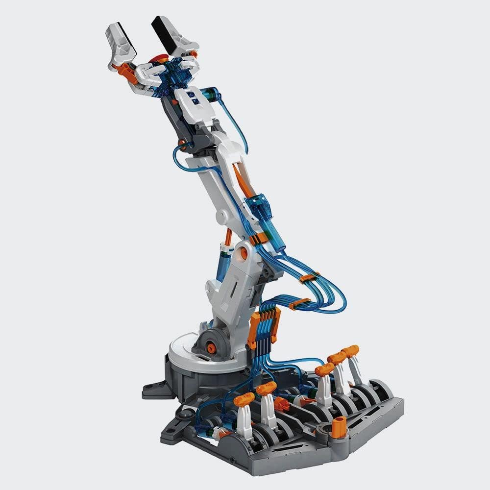
Constant pressure systems, unloaded. Same basic configuration as 'standard' CP system but the pump is unloaded to a low stand-by pressure when all valves are in neutral position. Not so fast response as standard CP but pump lifetime is prolonged. Pressure relief valves are used in several places in hydraulic machinery; on the return circuit to maintain a small amount of pressure for brakes, pilot lines, etc... On hydraulic cylinders, to prevent overloading and hydraulic line/seal rupture. On the hydraulic reservoir, to maintain a small positive pressure which excludes moisture and contamination. Components of a hydraulic system [sources (e.g. pumps), controls (e.g. valves) and actuators (e.g. cylinders)] need connections that will contain and direct the hydraulic fluid without leaking or losing the pressure that makes them work. In some cases, the components can be made to bolt together with fluid paths built-in. In more cases, though, rigid tubing or flexible hoses are used to direct the flow from one component to the next. Each component has entry and exit points for the fluid involved (called ports) sized according to how much fluid is expected to pass through it.A robotic arm that is hydraulically operated is usually controlled by springs filled with some fluid. It consists of various parts that are connected in a pre-designed manner. These are guided in a constrained way to obtain the required output. In the mechanism, each part of the robotic arm has been provided with a certain degree of freedom to move in a constrained way to guide other parts and also to collect items having very fewer weights and place them in other places. The complete mechanism includes a vertical link that is fixed. Some designs include dynamic flow channels on the fluid's return path that allow for a smaller reservoir.
Hydraulic machines use liquid fluid power to perform work. Heavy construction vehicles are a common example. In this type of machine, hydraulic fluid is pumped to various hydraulic motors and hydraulic cylinders throughout the machine and becomes pressurized according to the resistance present. The fluid is controlled directly or automatically by control valves and distributed through hoses, tubes, or pipes.For the hydraulic fluid to do work, it must flow to the actuator and/or motors, then return to a reservoir. The fluid is then filtered and re-pumped. The path taken by hydraulic fluid is called a hydraulic circuit of which there are several types. Hydraulic tubes are seamless steel precision pipes, specially manufactured for hydraulics. The tubes have standard sizes for different pressure ranges, with standard diameters up to 100mm. The tubes are supplied by manufacturers in lengths of 6 m, cleaned, oiled and plugged. The tubes are interconnected by different types of flanges (especially for the larger sizes and pressures), welding cones/nipples (with o-ring seal), several types of flare connection and by cut-rings. In larger sizes, hydraulic pipes are used. Direct joining of tubes by welding is not acceptable since the interior cannot be inspected. a b McNeil, Ian (1990). An Encyclopedia of the History of Technology. London: Routledge. pp. 961. ISBN 978-0-415-14792-7. Machines and Motors by Jon Richards and Ed Simpkins. Gareth Stevens/Wayland, 2016. A clearly written, illustrated guide to all kinds of powered machines. A good overview that will help children understand how simple machines power the bigger, real-world machines they see around them. It is ideally a metal arm with 4 to 6 joints and commonly used for various industrial applications. Industrial robot arms are like human arms and work in a similar way.
- Fruugo ID: 258392218-563234582
- EAN: 764486781913
-
Sold by: Fruugo